
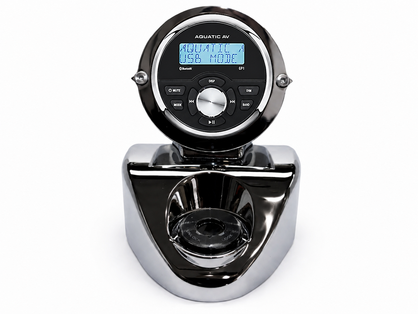
ATTENTION: Before you do anything, check your fork lock screws. Take a very small flat screwdriver and carefully pry off the plastic trim around the key on your fork lock. If you see screw heads, you’re golden. If there are smooth, round bolt heads with no slot for a tool, your bike has Security Breakaway Studs (the factory sometimes installed those to keep anyone from removing your lock).
The Fix: You will need to carefully drill and extract these studs to remove the nacelle cap. If you aren't comfortable with this step, this is the point where you should consult a local shop. The good news: Once they are out, toss them! Use the two high-quality screws we included in the kit for a standard, easy-to-service finish.
Phase 1: Preparation & Housing Access
1. Disconnect the Negative Lead on the Battery
- Paint Protection: Drape clean, soft moving blankets over:
- The Front Fender: To protect against dropped tools or the headlight assembly.
- The Fuel Tank: To prevent scratches from your belt buckle or reaching across the bike.
3. Headlight Removal
To install the GP1-RK, you need full access to the interior of the nacelle. This process varies slightly depending on your specific headlamp setup:
A. Trim Ring & Bezel
- Locate the screw at the very bottom of the headlight trim ring/bezel.
- Loosen the screw to unclamping the ring, then carefully pull the ring away from the nacelle. On some stock setups there is a spring at the top – be careful not to bend it.
B. Retaining the Headlamp
- Identify the Retaining Ring holding the glass/LED unit in place.
- Caution: You will see two sets of screws. Only remove the small retaining screws (usually 3 or 4) that hold the ring.
- DO NOT touch the larger adjustment screws used for headlamp aim (typically located at the 12, 3, or 9 o’clock positions).
C. Disconnect & Store
- Slowly pull the headlamp assembly forward.
- Unplug the main wiring harness (H4 connector or OEM LED plug).
- Place the headlamp in a safe area away from the work zone.
Phase 2: Remove Stock Handlebar Cap
1. Remove the Spear
Reach inside the nacelle through the headlight hole. There is a long threaded post (or a smooth stud, depending on model year) coming down from the chrome spear.
- The Action: Give that nut/stud a healthy shot of WD-40 or PB Blaster.
- Wait: Let it sit for 5–10 minutes. This isn't just a suggestion; it’s insurance against snapping the mounting stud off your chrome trim.
- The Tool: You’ll typically need a 10mm or 7/16" deep socket (or a nut driver).
- The Technique: * Earlier models use a stamped metal speed nut (flat and thin). Later models often use a flanged nyloc nut.
- Apply steady, gentle pressure. If it feels like it’s binding, turn it back in a quarter-turn, add more lube, and try again.
- Once the nut is off, the spear is held at the front by the nut you just removed and at the rear by a small tab or secondary screw under the handlebar cover.
- Pro Tip: As you lift the spear off, watch for any rubber gaskets or plastic spacers underneath. These prevent the chrome from vibrating against the nacelle paint. Keep them together with the spear.
2. Unscrew the Handlebar Cap
- Look at the top of the nacelle where the spear was just sitting. You will see a single large Phillips-head screw or a hex bolt (depending on the year) that was hidden directly under the front of that spear.
- Remove this screw completely.
- Pro-Tip: This screw is a prime candidate for falling into the nacelle. Keep your finger on it as it comes loose, or use a magnetic driver.
3. The Fork Lock Trim (Switch Cover)
Remove the plastic trim ring around the fork lock:
- On most Road Kings, there is a small "plate" or decal around the lock.
- On some years, this trim is held by two tiny screws; on others, it’s just a friction fit.
- The Action: Ensure the fork lock is in the unlocked position. If your model has a chrome collar around the lock, unscrew it to allow the handlebar cap to clear the switch.
4. Unscrew the Nacelle Cap
- Underneath the plastic trim ring there are two screws on most models. On some models, there are breakaway studs to prevent someone easily removing your fork lock (see the warning on Page 1.)
- With the main front screw removed and the fork lock trim cleared, grasp the handlebar cap and lift it up and slightly forward.
Phase 3: Installing the GP1-RK Handlebar Cap & Routing
Your new stereo head unit mounts exactly like your OEM handlebar cap, but cable management is everything. Go slow, and be precise.
1. Pre-Wiring & Protection
Before lowering the cap into place, prepare your connections:
- RCA Cables: If your kit has an amplifier, plug the supplied RCA cables into the back of the GP1-RK now.
- The "Tape Trick": Cut off the plastic protective caps from the RCA ends and secure the connection to the head unit with a wrap of electrical tape. This prevents them from vibrating loose inside the nacelle where you can't reach them.
2. The Routing Path (The "Left-Side" Rule)
To keep the install clean and prevent interference with the bike's throttle cables on the right, use the Left Side of the neck for your stere wiring:
- RCAs: Feed these into the nacelle on the left side, then out along the left side of the fuel tank toward your amp.
- AM/FM Antenna: Plug in the supplied hidden antenna and route it along that same left-side path.
- USB Port: If you plan to use the USB for phone charging or media, route the plug out near the top of the handlebars for easy access.
- GP1 Power Harness: Feed this down the left side alongside the RCAs.
- Speaker Leads: if your stereo kit has the 3.5” Handlebar Speaker Pods, drop one speaker lead down the left side and one down the right side to reach your respective handlebar speakers. If you are not using the handlebar speakers at this time, you can safely cable tie these leads to the harness inside the nacelle to keep them hidden.
3. Seating the Nacelle Cap
- Carefully lower the new GP1-RK cap into position over the handlebar risers.
- Watch for Pinches: As the cap drops, ensure no wires are caught between the cap and the handlebars or the nacelle halves. Everything should slide into place without force.
- Secure the front fastener (the one previously hidden by the spear) to lock the cap down.
CRITICAL SAFETY CHECK (The "Swing Test")
Before you tighten everything down and move to the next step, you must perform a clearance check:
- Check the Lock: Slowly turn the handlebars all the way to the Left Stop, then all the way to the Right Stop.
- Verify: Ensure no wires are being stretched tight, "tugged" out of the head unit, or pinched against the frame or fork stops.
- WARNING: Failure to ensure full, unobstructed movement of the handlebars can lead to a loss of control. If it pulls, re-route it.
Does the movement feel smooth and "tangle-free"? If so, we’re ready to put that chrome spear back on and seal the top of the nacelle!
Phase 4: Powering the GP1-RK
Now that the head unit is mounted, we need to run the main power harness back to the battery. This harness features a dedicated on-off toggle switch to prevent parasitic draw during storage.
1. Routing the Harness
Run the GP1 Power Harness from the nacelle back toward the seat along the left side of the bike. You have two options:
- The "Clean" Route: Feed it under the fuel tank for a completely hidden look.
- The "Easy" Route: Run it along the outer frame rail. If you choose this, use black zip ties every 4–6 inches to keep it tight and professional.
- Tip: Ensure the harness stays clear of the engine's cooling fins.
2. Mounting the Storage Toggle Switch
The positive lead features an integrated on-off toggle switch with 3M adhesive backing.
- The Purpose: The GP1-RK pulls a tiny amount of "memory" current even when off. If the bike sits for more than a few days, flip this switch to OFF to save your battery.
- The "No-Tape" Rule: Do NOT rely on the 3M tape on the switch to support the weight of the wiring harness. Use zip ties on both sides of the switch to hard-mount the wires to the frame. The 3M tape is only to keep the switch face from spinning or rattling.
- Placement: Stick it somewhere accessible but hidden — usually on the side of the frame, where the tank and seat meet.
3. Connecting to the Battery (Don't Cross the Streams!)
Locate your battery terminals.
- Positive (+): This is the lead with the Yellow and Red wires and the toggle switch. Connect this to the Positive (+) battery post.
- Negative (-): This is the Black wire. Connect this to the Negative (-) battery post.
- Safety Note: Always connect Positive first, then Negative, to avoid accidental sparks against the frame.
4. Test
Before you zip-tie the final slack and put the seat back on:
- Ensure the new toggle switch to the ON position – the GP1 screen will display the time.
- Press the power button on the GP1-RK faceplate.
- Verification: The screen should light up!
Final Connection Check
Once you've confirmed power, go back and "clip the tails" off all your zip ties. Make sure the battery bolts are snug—vibration is the #1 cause of "ghost" power issues.
Phase 5: Re-Assembly & Sealing the Nacelle
With your wiring routed, the "Swing Test" passed, and the GP1-RK cap seated, it’s time to close up the housing. We are moving in the exact reverse order of teardown.
1. Reinstalling the Chrome Spear
- Alignment: Carefully slide the rear tab of the spear into its slot (or over its rear screw) and lower the front threaded stud through the hole in the nacelle.
- The Speed Nut: Reach inside the headlight opening. Hand-thread the speed nut (or flanged nut) onto the spear’s stud.
- Tighten: Use your 10mm or 7/16" socket to snug it down.
- Pro-Tip: Do not over-torque! These studs are notorious for snapping. Snug is enough to prevent vibration.
2. Headlight Reconnection
Before the glass goes back in, ensure your interior wiring is tucked away from the back of the headlamp bucket to allow for heat dissipation.
- Plug in the Harness: Reconnect the H4 or OEM LED plug to the back of the headlamp.
- The "Test Fire": Before screwing anything in, turn the ignition to ACC. Verify that the headlight (High and Low beam) and the GP1-RK head unit both power up correctly.
3. Setting the Headlamp & Retaining Ring
- Position the Lamp: Set the headlamp back into the bucket. Most have "notches" that ensure it sits level.
- Retaining Ring: Place the thin metal ring over the lamp.
- Secure: Reinstall the small retaining screws you removed earlier.
- Reminder: Avoid touching the larger adjustment/aiming screws.
4. The Outer Trim Ring (Bezel)
- Slide the thick chrome trim ring over the assembly.
- The Clamp: Align the screw at the 6 o’clock position.
- Final Tighten: Tighten the screw until the ring is rock-solid and won't rotate or rattle.
The "Park & Party" Advantage:
- No Keys Needed: You don't have to leave your bike in ACC mode to listen to your music.
- Save the Bike's Battery: On a stock setup, running the radio in "Accessory" mode keeps the bike’s ECM, lights, and gauges powered up, which drains the battery fast. With this setup, only the stereo is pulling power.
- The "Kill Switch" Security: When you’re done for the day or parking the bike for the week, just flip that hidden toggle to OFF. It’s the ultimate fail-safe to ensure your battery is 100% ready to crank the next time you hit the starter.
System Operation & Settings
Now that the hardware is bolted down and the power is flowing, it’s time to dial in your sound.
Refer to the included Aquatic AV GP1 User Manual for all specific operating instructions. The manual is your go-to guide for:
- Bluetooth Pairing: Connecting your phone for wireless music.
- AM/FM Presets: Saving your favorite local stations.
- USB Media: Navigating folders if you're using a thumb drive.
Pro-Tip: Keep the Aquatic AV manual in your saddlebag or tool kit. If you ever need to reset the unit or tweak a setting on a long road trip, you’ll be glad you have it.
CRITICAL: Do Not Adjust the EQ Settings
Your GP1-RK system has been professionally pre-tuned for maximum performance and safety.
- The Calibration: The internal crossover and Frequency settings have been locked in to ensure your speakers can hit 100+ dB clearly without distortion.
- The Risk: Changing the digital EQ (Bass/Treble/Loudness) inside the Aquatic AV menu can override these safety limits. Pushing the "Bass" or "Loud" settings at high volumes will cause clipping and can lead to permanent speaker failure.
- The Rule: Leave the EQ at "FLAT" or "OFF." If you want more punch, simply turn up the volume—the system is already optimized to give you the best possible sound for the open road.
Parts Included:
- GP1-RK 1998-2013 or GP1-RK2014
- GP1-RK Power Harness
- AM/FM Hidden Antenna
- 2 x Screws for Lock (10-24x1/2” long, 18-8 Stainless Steel Flat Screws)