
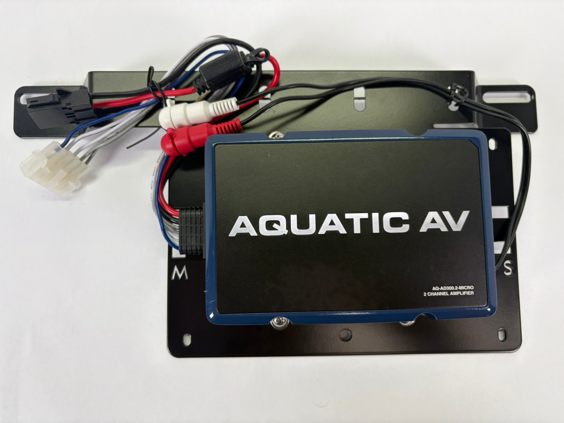
For Aquatic AV AD300.2 Micro 2-Channel Amplifier (for use with Aquatic AV HS113 ULTRA+ RGB Speakers)
Softail Models
Please read the complete instructions before you begin.
Mounting the RoadLock Bracket
Install the amplifier in the Left-Hand (Clutch Side) saddlebag. This is the "low side" when parked on the kickstand, leaving the right side bag free for your daily gear.
On Softail models, simply remove the hardware securing the bag to the bike, slip the bracket over the mount holes, and re-attach the hardware.
Important: Verify that all mounting hardware provides sufficient thread engagement after installation of the amplifier bracket. On models that use mounting bolts, ensure the bolts engage an adequate number of threads in the threaded mounting points. On models that use studs and nuts, ensure the nuts fully engage the studs and can be tightened securely. If adequate thread engagement cannot be achieved using the original hardware, longer fasteners should be used.
Routing the Main Power Harness
The main power harness must be routed from the battery area to the saddlebag where the amplifier is mounted.
Most seats offer sufficient clearance between the rear of the seat and the rear fender to route the harness beneath the seat and out toward the saddlebag. This is typically the simplest installation method and requires no modification to the motorcycle. Ensure the harness is protected from sharp edges and moving components, and verify that the seat does not pinch or place excessive pressure on the wiring when reinstalled. There is a small piece of rigid plastic sheathing included that can be fixed to the wire, if needed, with electrical tape.
If insufficient clearance exists beneath the seat, the connector may be disassembled and the wires routed down between the frame rail and oil tank before entering the saddlebag.
An additional connector has been supplied with the kit in case it is required. Carefully cut the cable tie (careful not to nick the wires), and remove the plastic connector body. Route the wires through the desired path, and reinstall the connector body once the harness is in position.
Regardless of the routing method used, ensure the harness is secured properly and cannot be pinched, chafed, or damaged by suspension movement, seat mounting hardware, or contact with anything hot.
Routing into the Saddlebag
Unlike a Touring model, where installation typically requires drilling holes through the rear of the saddlebag, Softail models offer two possible methods for routing the rear speaker wiring. Either approach may be used, depending on customer preference.
Option 1 – Through the Rear of the Saddlebag
The rear speaker wires may be routed through ¾” holes drilled in the back of the saddlebag and plugged with the supplied grommets, similar to a Touring installation.
Important: The speaker connectors will fit through the grommets only before the grommets are installed in the bags. Once the grommets are in the bags, the sides of the grommets become too rigid to pass the connector through.
The power harness connector can be easily disassembled. Simply cut the cable tie (carefully, do not nick the wire) remove the terminals from the connector body, route the wires through the grommet, and reinstall the terminals and connector body after the wires are in place. An extra connector has been supplied with the kit if required. Some black RTV silicone should be used around the wires to ensure complete water protection.
This method provides the cleanest and most permanent installation.
Option 2 – Routing Between the Lid and Bag (No Drilling Required)
Because Softail soft leather saddlebag lids generally have sufficient flexibility and clearance, the rear speaker wires may simply be routed out the rear of the lid and down into the saddlebag without drilling any holes.
Use a piece of the supplied fiberglass braided sheathing to protect the wiring at the lid, and ensure there is adequate slack to accommodate opening and closing of the lid.
Carefully inspect the routing to ensure the wires are not pinched or subjected to excessive strain.
This method allows the installation to be completed without permanently modifying the saddlebags.
Either method is acceptable. Choose the routing approach that best suits your preferences and desired level of permanence.
Routing the Signal (RCA)
Identify the RCA leads from the Head Unit. For best noise rejection and a clean signal from the head unit to the saddlebag, route the RCA cable underneath the fuel tank or along the left (clutch) side of the bike along the frame under the tank, then under the seat, and down into the saddlebag.
Direct RCA Connection
This system uses the AD300.2's two channels in normal stereo mode. No bridging and no RCA Y-splitters are used.
Simply connect the colour-matched RCA plugs from the harness directly to the amplifier inputs: red to red and silver/white to white.
That's it. The signal and speaker wiring are pre-configured for a simple plug-and-play installation. No additional wiring changes or amplifier adjustments are required.
Speaker Wiring Connections (Stereo Mode)
Your speaker connectors are pre-wired. Simply connect the speaker pigtails to the speaker plugs on the amplifier. By convention, the white/gray pigtail is used for the left speaker and the green/purple pigtail for the right. Following this convention will preserve the stereo image.
Final Power Assembly & Battery Connection
Your amplifier is pre-wired. Simply plug the black HRB connector from the power harness into the amplifier power plug.
Ensure the fuse is removed before connecting the battery leads. Install the fuse only after all wiring connections have been completed and verified.
Route the power and ground leads to the battery and connect the terminals — positive first, then negative.
Remote Wire: Connect the blue trigger wire from the amplifier to the blue wire on the GP1 power harness. This allows the amplifier to turn on and off automatically with the head unit.
Final Function Check
Before closing the saddlebag and reinstalling the seat:
- Verify both speakers are operating.
- Verify the amplifier powers on and off with the head unit.
- Ensure no wires are pinched by the saddlebag lid.
- Confirm the saddlebag closes normally. If something does not look right, stop and determine why before proceeding.
The "Goldilocks" Gain Setting
Your complete system has been bench tested, and the gain, crossover and bass boost settings have been set before it was shipped to you. Changing these settings can cause distortion or speaker damage. Damage resulting from adjustment of these settings is not covered under warranty.
The GP1 settings have also been set. These are easily changed to suit your tastes, but excessive bass can damage speakers, and with the low-frequency engine and wind noise on a motorcycle, deep bass is largely masked while riding.
Pro-Tip: If the system sounds too "thin" in your driveway, remember that it was tuned for highway use, where mid-range and high frequencies are what cut through engine and wind noise.
Why We Limit Bass
It is tempting to lower the crossover frequency or add bass boost to get more "thump" while parked. Don't do it.
- Acoustic Masking: On a motorcycle, deep bass is the first thing to disappear.
- Exhaust and wind noise mask much of the low-frequency content, so you will not hear the same bass at speed that you hear while parked. Speaker Protection: The HS113 is a 6.5" full-range speaker rated at 75W RMS per speaker. Pushing deep bass or excessive boost into the speakers at high volume increases cone excursion and can damage them. Concentrated Energy: By using the amplifier's High-Pass Filter at approximately 80Hz with Bass Boost set to 0dB, the speakers can focus more of their available power on the mids and highs that are most useful on the road.
For future reference, your settings are as follows:
1. Gain Control (Input Sensitivity)
- Physical Dial Position: Bench-set. Do not adjust.
Target Voltage (HS113 ULTRA+ RGB): 17.3V AC per channel (75W RMS into 4 Ohms, measured with a 1kHz test tone).
2. Crossover (Frequency)
- Switch Position: HPF (High Pass Filter).
- Crossover Frequency: Approximately 80Hz.
- Purpose: Filters unnecessary deep bass below approximately 80Hz to reduce speaker excursion and preserve output at highway volume.
- 3. Bass Boost Setting: 0dB (OFF).
- 4. Audio Source (Head Unit)
- Max Clean Volume: 36 (on a 0-40 scale).
- EQ Settings: Bass OFF (or Flat). Loudness: OFF. This helps ensure maximum clean volume without pushing the amplifier or speakers into a damaging clipping condition.
- THE GOLDEN RULE: Do NOT touch the Gain, Crossover or Bass Boost controls! PARTS INCLUDED: 1 x Aquatic AV AD300.2 Micro 2-Channel Amplifier, pre-installed & wired 1 x RoadLock Amplifier Bracket 1 x RCA Lead (connect to Head Unit – run to saddlebag)