
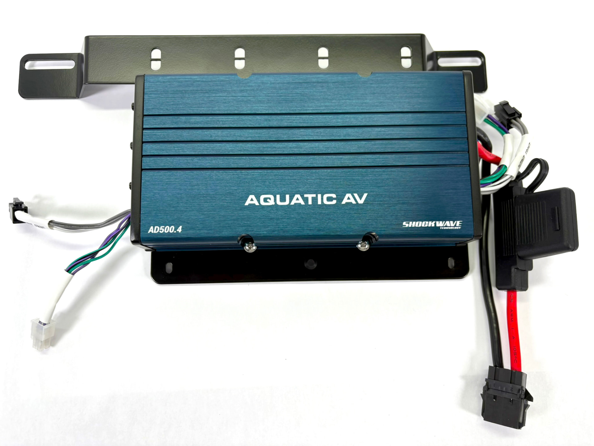
For Aquatic AV AD500.4 Micro Amplifier (for use with Aquatic AV HS116 Neo Speakers)
Please read the complete instructions before you begin.
Before you begin, we recommend that you have on hand:
- A Step Drill Bit (unibit)
- A small tube of Black RTV Silicone on hand to seal the grommets in your saddlebag, once installed.
Drilling & Grommet Installation
Pro Tip: We are installing the amplifier in the Left-Hand (Clutch Side) saddlebag. This is the "low side" when parked on the kickstand, leaving the high-side bag free for your daily gear.
Step 1: Remove the Factory Hardware
- Open the left saddlebag and remove it from the bike.
Precision Note: Use a Step Drill Bit (Unibit) for the cleanest holes. Standard twist bits can "grab" the fiberglass or plastic and cause cracking.
Understanding The Routing Path
Pro tip: We kept the grommets to the smallest size possible for best moisture sealing. The connectors go through the grommets BEFORE the grommets are installed in the bag. Once the grommets are in the panel, there is less “give” to get the connectors through.
- Grommet No.1 = RCAs: These go through the first grommet. If you feed one through first, the second one will slide across the wire and through the grommet.
- Grommet No.2/3 = Speakers + Power & Ground: Feed the mini Deutsch Connectors on the Speaker Leads (from the 6.5” Pods) through the grommet first. Then, slide the amplifier power, then amplifier ground through.
Step 1: Mark Your Location
- Identify a spot on the back wall of the left saddlebag, near the front (closest to the rider).
- Stay high, nearly level with the mounting hardware for the saddlebag. This keeps the wires high and dry.
- Space the two marks at least 2 inches apart to ensure the grommet flanges don't overlap( either one on top of the other, or side by side)
Step 2: Drilling
Note: The 1998-2013 and 2014-2024 saddlebags have different material thickness. Please select the appropriate size drill for Amp Power and Speaker Wire for the year of your bike.
| Bag Year | Hole (Unibit Size) |
|---|---|
| 1998–2013 | 3/4” |
| 2014–Present | 13/16” |
Note: While our silicone grommets are engineered to lock perfectly onto the OEM HarleyDavidson saddlebags , aftermarket bags with thicker fiberglass or thinner plastic walls may require you to source alternate grommets.
Replacing the Bag and Securing the Saddlebag & Amp Bracket
Before reinstalling the bag on the bike, gently pry the factory Dzus spring clips off the saddlebag brackets with a flat blade screwdriver. Set them aside, you won’t be needing them.
Step 2: Install the RoadLock Bolt Clips
- Take the two Stainless Steel Bolt Clips from your hardware kit.
- Slide them onto the saddlebag bracket where the old clips were located. Ensure the threaded "nut" side is facing the inside of the bike.
Step 3: Mounting the RoadLock Bracket
- Set the saddlebag back onto the lower support rail of the bike.
- Place the RoadLock Amplifier Bracket inside the bag, aligning its mounting slots with the holes in the saddlebag and the new clips on the frame.
- Assemble your Stainless Hardware in this specific order for each hole:
- The Large Flat Washer (goes against the rubber cushion/bracket)
- The Lockwasher goes directly under the bolt head
- Thread the bolt through the bracket and bag into the frame clip.
Step 4: Tighten and Secure
- Using a wrench or socket, tighten the bolts until the lock washer is flat and the bracket is rock-solid.
- The Result: Your bag is now physically bolted to the frame. Unlike the factory pins, these cannot be removed with needle-nose pliers from the outside, protecting your bag and your high-end amplifier from theft.
Now that the amplifier is securely mounted and the wires are routed into the bag, it’s time to complete the audio connections.
Routing the Signal (RCA & Speaker)
Identify the RCA leads from the Head Unit. To prevent "alternator whine" and ensure a clean signal from the head unit to the saddlebag, follow this specific path:
- The Headstock: Start at the radio and secure the RCAs inside the nacelle to the factory wire bundles at the neck using zip ties, ensuring enough slack for the handlebars to lock full-left and full-right without tugging the cables.
- Under the Tank: Follow the frame rail on the Left (Clutch) Side. Use the existing plastic wire troughs if there is room, or zip-tie the RCAs securely to the top of the frame rail so they aren't pinched when the tank is bolted down.
- Left Frame Rail (Under Seat): Continue along the left rail, keeping the RCAs physically separated from the amp power harness as much as possible.
- Into the Bag: Route the RCAs through the grommet one at a time.
The Power/Signal Split: To prevent electromagnetic interference (EMI) or "alternator whine," we keep the RCA cables and speaker wires in one grommet, physically separated from the high-current 8 AWG power lines in the other grommets Installation: Only now that the bag and the amp are on the bike, push the RCAs and speaker connectors through the Silicone Rubber Grommets before you pop them into the hole. Ensure that the outer flange seals against the bag.
RCA Y-Splitters
You will be using Y-Splitters for the RCA leads because you are running 2 speakers in bridged mode. Follow these instructions carefully, to achieve amplifier bridging.
Inside the saddlebag, you will now have a the Left (White) and Right (Red) RCA output leads coming from the GP1 head unit.
- Plug one RCA Y-splitter into the Left (White) RCA lead from the GP1. Connect both male ends of this splitter into the "INPUT REAR" (Green/Purple pigtail).
- Plug the second RCA Y-splitter into the Right (Red) RCA lead from the GP1. Connect both male ends of this splitter into the "INPUT FRONT" (White/Grey pigtail).
You are now using the entire “Rear” power of the amp for your left speaker, and the entire “Front” power of the amp for your right speaker.
Ensure the physical Input Level switch on the side of the amplifier is set to "Low" (RCA mode).
Speaker Wiring Connections (Bridged Mode)
Your connectors are pre-wired. You just have to connect your speakers to the labeled wire pigtails as follows:
- Left Speaker: Connect to the Green (+) and Purple (-) wires on the REAR output.
- Right Speaker: Connect to the White (+) and Grey (-) wires on the FRONT output. For your reference only, this is how the connectors are wired from the speakers: Speaker Location Harness Wire (Speaker Side)
| Speaker Location | Harness Wire (Speaker Side) | Amp Wire (Output Side) | Amp Label Reference |
|---|---|---|---|
| LEFT SPEAKER | White (+) | Green | BRIDGED+ / OUTPUT REAR LEFT (POS) |
| LEFT SPEAKER | Black (-) | Purple | OUTPUT REAR LEFT (NEG) |
| RIGHT SPEAKER | White (+) | White | OUTPUT FRONT RIGHT (POS) |
| RIGHT SPEAKER | Black (-) | Grey | BRIDGED- / OUTPUT FRONT RIGHT (NEG) |
Step 4: Final Protection
- DO NOT Adjust EQ Settings: The system is pre-tuned for the 444-Watt "Park & Party" profile.
- Adjusting these settings manually can lead to speaker damage and will void the warranty .
Final Power Assembly & Battery Connection
With the wires routed through the grommets, you are ready to assemble the main power disconnect and "fire up" the system.
1. Power Connector Assembly (Harness Side)
Gently pull the wires from the Black Plug on the Amplifier Power Harness, noting the orientation (orientation matters!).
Slide the wires with the terminals through the grommet. Then, push the wires back into the black plug until they slick into place, to re-make the connector.
- Ensure that RED on the harness goes to the RED wire on the amp, and BLACK on the harness goes to the BLACK wire on the amp.
2. Connecting the Amplifier
- Remote Wire: Connect the Blue "Wake Up" wire from the amp to the blue wire on the GP1 power harness so the amp turns on and off with the ignition.
If there is any open space in the grommet after routing your wires, apply a small bead of Black RTV Silicone to the gap once the installation is complete. This prevents water from traveling down the harness and into your electronic connections. Allow it to skin over for at least an hour before riding.
Battery Connection & Power-Up
SAFETY FIRST: Ensure the main fuse is REMOVED from the fuse holder before beginning. Do not insert the fuse until the very last step.
| Order | Action | Connection Point |
|---|---|---|
| First | Positive Connection | Connect the RED ring terminal to the Positive (+) battery post. |
| Second | Negative Connection | Connect the BLACK ring terminal to the Negative (-) battery post. |
| Third | Remote Turn-On | Connect the thin Blue wire to the blue wire in the GP1 Power Harness |
Final Power-Up
- Inspect: Confirm that both terminal bolts are tight and that no 8 AWG wire is pinched under the seat or frame.
- Fuse Insertion: Insert the provided fuse into the waterproof fuse holder.
- Test: Turn the bike’s ignition to "ACC" or "ON." The amplifier should power up.
The "Goldilocks" Gain Setting
Your Amplifier has been pre-calibrated and bench-tested specifically for the 6.5" pods included in this kit (31.62V AC for the HS.116 NEO) – roughly between 10 o’clock and 12 o’clock on the gain dial. Please do not change these settings. The gain dial is not a volume knob – it is an input sensitivity match. If you turn the knob past the 12 o’clock position, you will likely hit the "clipping" point where the signal distorts, which is what kills those HS116 Neo speakers.
Pro-Tip: If the system sounds too "thin" in your driveway, remember that it was tuned for the highway to produce mids and highs.
Why We Limit Bass (The Highway Reality) It is tempting to turn the Frequency down to get more "thump" while parked. Don't do it.
- Acoustic Cancellation: On a motorcycle, bass is the first thing to die. Between exhaust roar and wind noise, low-frequency waves (below 80Hz) are physically canceled out—you won't hear them at speed anyway.
- Speaker Protection: Pushing deep bass into 6.5" pods at high volume causes excessive "excursion," which can physically tear the speaker cone.
- Concentrated Energy: By keeping the HPF (High Pass Filter) dial at 9 o'clock, your speakers focus all their energy on the mid-range and vocals that actually cut through the wind at 108+ dB.
For future reference, your settings are as follows:
1. Gain Control (Input Sensitivity)
- Physical Dial Position: Between 10-12 O’Clock (No higher than straight up).
- Target Voltage (HS.116 Neo): 31.6V AC (Measured at 1kHz at Head Unit Volume 36).
2. Crossover (Frequency)
- Switch Position: HPF (High Pass Filter).
- The Frequency Dial: Physical Dial Position: 9 O’Clock.
- Estimated Frequency: ~80Hz – 90Hz.
- Purpose: This cuts out the "muddy" sub-bass, allowing the 6.5" pods to play significantly louder (108+ dB) without hitting their physical excursion limits.
3. Audio Source (Head Unit)
- Max Clean Volume: 36 (on a 0-40 scale).
- EQ Settings: Bass OFF (or Flat).
- Loudness: OFF.
This ensures maximum volume without hitting the "clipping" zone that destroys voice coils.
THE GOLDEN RULE: Do NOT touch the Gain or Crossover dials!
- Warranty Note: Tampering with the security seals on the gain dials voids your warranty.
PARTS INCLUDED:
- 1 x Aquatic AV AD500.4 Amplifier, pre-installed & Wired
- 1 x RoadLock Amplifier Bracket
- 1 x Hardware Kit (2x bolts, 2x lockwashers, 2x flat washers)
- 1 x Grommet Pack (1998-13 or 2014-later)
- 1 x HRB Power Plug
- 1 x RCA Lead (connect to Head Unit – run to saddlebag)
- 2 x RCA Y Splitters (for inside saddlebag)
- 2 x 4” UV Resistant Cable Ties